Water  desalination

INNOVATIVE, NEXT GENERATION TECHNOLOGY FOR DESALINATION EQUIPMENT - EMSF

EMSF = Environmental Multi-Stage Flash
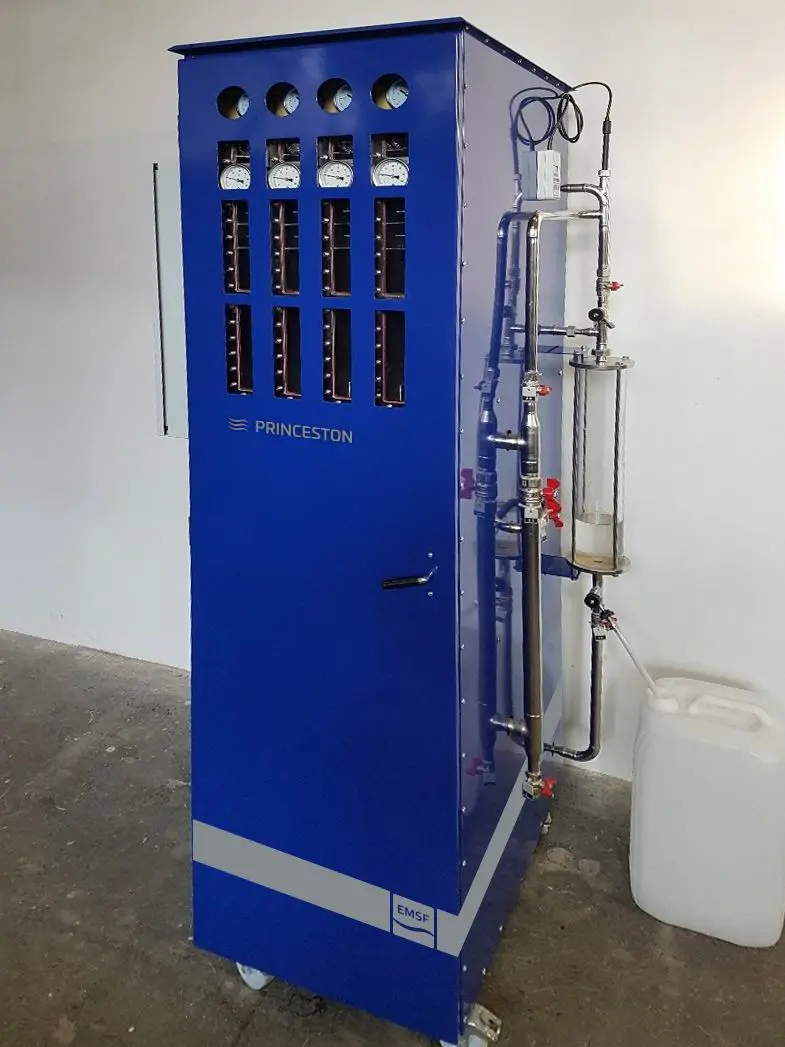
EMSF is innovative technology for production of very clean, drinkable water using vacuum distillation
Key parameters
  • allows for production of baby-suitable water and cleans the water to a valuelower than 1 ppm (parts per million). That is one millionth of dissolved substances.Meanwhile, when using a traditional method such as reverse osmosis (RO), it isdifficult to keep the output value at even 300 ppm (and this happens only with theuse of brand-new filters and a well-configured device).
  • reduces pressure inside the device, leading to a marked decrease in the water‘sboiling point; thus, decreasing energy consumption and the cost of waterproduced.
  • EMSF is able to utilize fordesalination processconventional (thermic,nuclear, hydro) as well asalternative (solar, wind,etc.) sources of power.
  • The biggest advantage isthe possible usage of wasteheat which allows toproduce high-qualitydrinking water for close toZERO running cost.
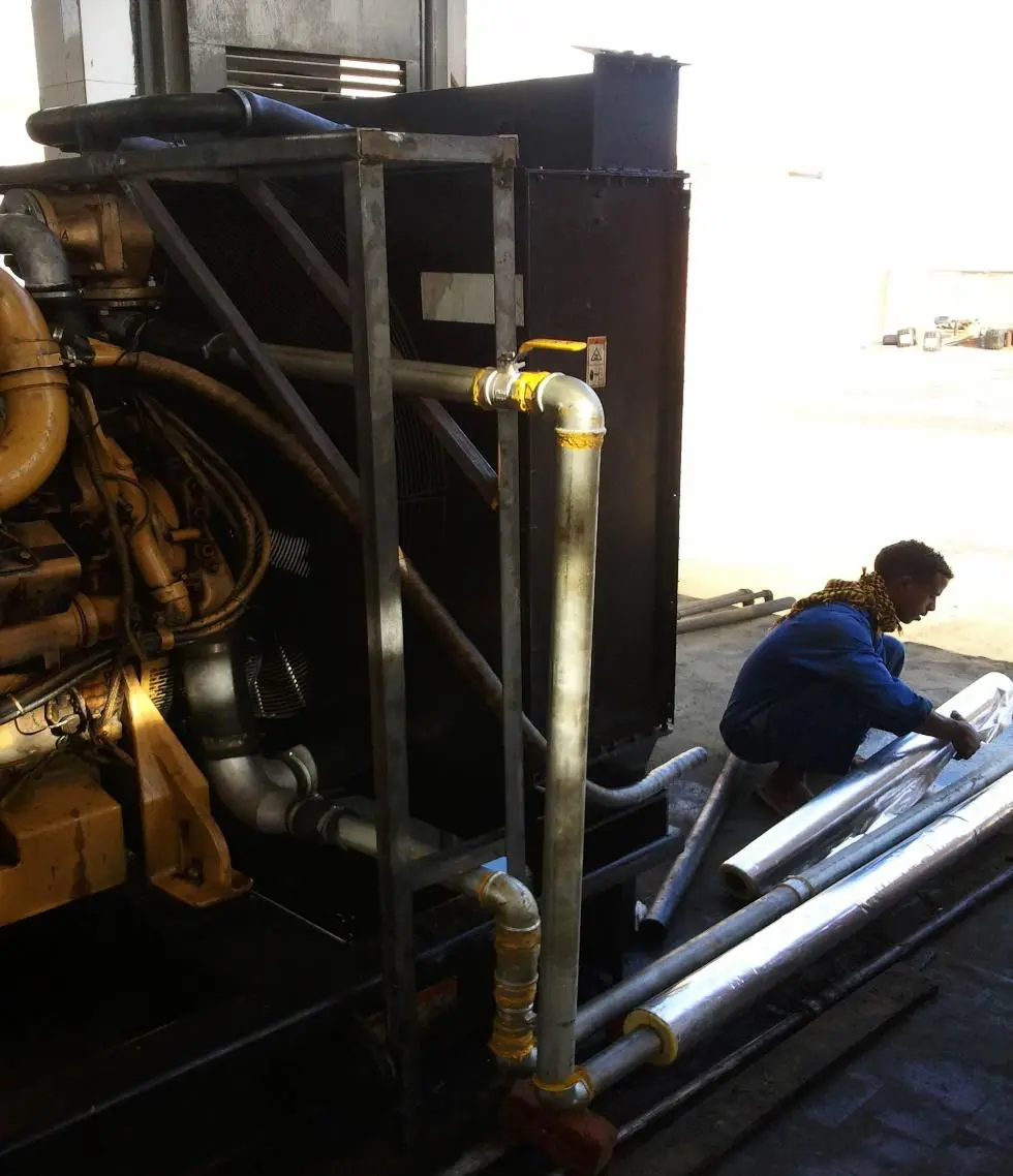
  • The technological design enables use of waste heat from all sorts of technologicalequipment: diesel generators, transformer stations, engine rooms, engines, heatexchangers, incinerators, etc.; allowing for the cheapest water production possible,while not producing additional CO².
  • As with all thorough water cleaning devices, it is advisable to have thewater re-mineralized if it is meant for drinking.
  • The technology can also be regulated in order to achieve the desiredlevel of mineral preservation from the original (input) water. Thisfurther distinguishes it from other traditional technologies.
  • Other uses include the addition of fertilizers and trace elements toclean (output) water designated for agricultural irrigation
Connection of an EMSF unit to awaste heat source (diesel generator)

DESCRIPTION OF THE UNIT AND PROCESS

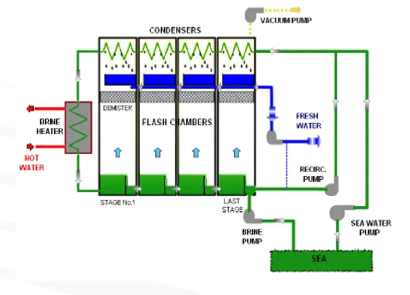
The recirculation stream flows from the n-2 stage to the first stage where it is heated gradually by the condensation vapor.
After leaving the first-stage condenser, water flows through the brine heater, where the heat input to the unit causes a further temperature increase.

The well water leaves the brine heater at the brine top temperature (BTT – approx. 80 °C). Up to this point, the pressure of the well water is above atmospheric pressure and therefore below boiling pressure.

The well water is then directed into the first stage of the unit, which is at a pressure below the boiling pressure. In order to return to a state of equilibrium, part of the well water is flashed off such that the saturation temperature corresponds to the pressure in the stage. The distillation process operates from low vacuum in the first stage to high vacuum in the last stage, with stage-to-stage pressure and temperature differentials being the key to the repeated flashing.
The flashed vapor is drawn into the condenser where it is condensed and collected as a distillate. The distillate is drawn through from the first stage to the last stage condenser, where it is discharged by the distillate pump.

Part of the brine (approx. 2/3) from the last stage is mixed with raw well water and then pumped again by a recirculation pump into the distillation system. The second part of the brine (approx. 1/3) is discharged by the brine pump.

The non-condensable gases released during the various stages are discharged by the vacuum pump. The fresh water is continuously measured. If the salinity exceeds the acceptable limit, the distillate is automatically dumped into the recirculation brine.

THE BASIC MODEL SERIES

  • Distillation units with brine recirculation
  • The device is a modular system with a standard capacity ranging from 1 to 200m3of fresh water/day
  • Individual units can be set up and arranged as needed. This flexibility is especiallyconvenient for use on ships and in other confined spaces. Conversely, the sameprocess can be used to increase capacity
  • The device is nearly maintenance-free: with planned shutdowns for simplecleaning being the only exception. The device‘s operating time is 350 days/year
  • Technological or building preparation is not needed: the EMSF unit can bedelivered in a standard container

ADVANTAGES

  • Easily expandable modular design
  • Fast manufacturing (ready within 2-4 months after ordering)
  • Simple and fully automatic operation
  • Very easy maintenance
  • Compact, sturdy construction
  • Low consumption of cooling water
  • Operates at a top brine temperature < 100 °C to minimize scaling and to preventcorrosion
  • Minimal down time (higher availability factor)
  • Components the come into contact with sea water or fresh water aremanufactured from corrosion-resistant materials

Main disadvantages of Reverse Osmosis when compared with EMSF

  • Acquisition cost of Reverse Osmosis (RO) is higher than EMSF and if there is a waste heat sourceavailable on site RO has also significantly higher running costs than the EMSF
  • EMSF produces 100 to 300 times cleaner water (in terms of depleted salts)
  • RO is more susceptible to cleanliness of the inlet water. Besides its own filter membrane it stillneeds pre-filtration and also uses activated charcoal which increases the running costs of theconsumables
  • RO is more limited by the salinity of the inlet water. If the salinity of raw water is increased alsothe pump capacity must be increased (need of installation of more powerful pumps)
  • RO is limited by inlet water temperature, its functionality is guaranteed only up to watertemperature + 30°C
  • RO manufacturers are unable to produce small units with capacity of only few m3/day
  • RO has increased demands on time-out for filter regeneration (backflow of the filters) and theassociated high consumption of purified water for self-regeneration and also for pressurizedpump energy
  • RO needs a qualified operator for its own operation, regular replacement of filter membranes andcan be installed only in a clean operating environment.
  • RO needs chemicals (acids) for its washouts and these acids must be subsequently disposed

Fundamental difference is quality of output water.

The long term use of water treated by RO for irrigation leads to gradual soil degradation due to the irreplaceable proportion of salt in irrigation water.

This can be illustrated by the place on the photo, where irreversible soil degradation has occurred due to usage of low-salt irrigation water.

Succesfull use cases

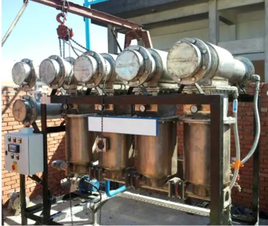
APPLICATION of EMSF 20 in Egypt
  • Installed at EL Quseir, Egy
  • Capacity: 20 m3/day
  • Salinity: 10-15 ppm
DESIGN PARAMETRES
Tube length: 1,3 [m]
Tube diameter: 19x1 [mm]
Tube material: CuNi90/10
Number of tubes: 10
Number of stages: 4
Capacity: 20 [m3/day]
Energy consump.:  313 [kW]

Ready to explore our solutions? 

Let's schedule a meeting or call.
(c) 2024 NWT Holding s.r.o.